Integration Broker - Part 1 - Configuration
This posting will cover the configuration of Integration Broker for integration of two Peoplesoft systems.
For this posting, we have two installations of PeopleSoft Demo Financial and
Supply Chain Management 9.2 as follows.

192.168.1.186 fscm92.ps.com
192.168.56.101 fscm9205demo.ps.com
When the PeopleSoft 9.2 Image was deployed on Virtual Box, it created a virtual machine with all the required components like Database, Application server, Web server and Process Scheduler. Let us start the virtual machine so all the four servers mentioned above will start automatically. The Virtual machine comes preconfigured with a number of things. An Enterprise installation will not have that advantage. So we will go through all the steps even if they are not required on Virtual Machine.
The following major steps will be performed.
Step #1) Configuring the Application Server on installation#1
Step #2) Configuring the Application Server on installation#2
Step #3) Renaming the default local node on installation#1
Step #4) Renaming the default local node on installation#2
Step #5) Adding remote node on installation#1
Step #6) Adding remote node on installation#2
Step #7) Configuring using the delivered WorkCenter on installation#1
Step #8) Configuring using the delivered WorkCenter on installation#2
Let us login to the Linux command shell as root. For administering the
PeopleSoft 9.2 application installed on Virtual Box we will use the Peoplesoft
userid psadm2. At the command prompt for root switch to user psadm2. Change the
directory to the one pointed by PS_CFG_HOME/appserv. In our case PS_CFG_HOME is
pointing to /home/psadm2/psft/pt/8.53. This location has the default
application server domain (APPDOM) files.

Start psadmin from here.
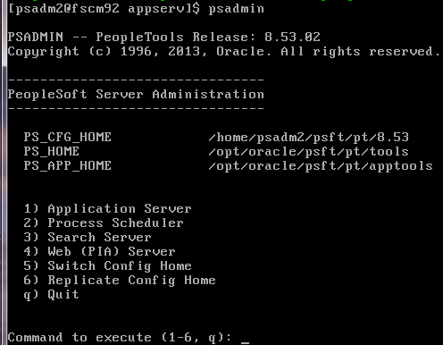
Select option 1 for Application Server.
Select option 1 for Administer a Domain.
Select option 1 for the domain (APPDOM in my case).
Select option 2 for Domain shutdown menu.
Select option 1 for Normal shutdown.

Select option 4 for Configuration of Domain. Type ‘y’ for shutdown of domain.

Make sure that
Option 1) Pub/Sub Servers is set to Yes
Option 4) Jolt is set to Yes
Option 27) JSL Port is set (to 9000 in our case)
If you made change to any option, select option 13) Load config as shown. Or
else, select q to quit that menu.
You will be at the Domain Administration menu again. Select option 7 for
Messaging Server Administration menu.

If no messaging server is listed, select option 1) Create a new messaging server.
Select option 1) Publication Broker.
Enter the name of the server (as FSCMSG).
Enter the messaging queues as 25.

Select option q) to go back to the Domain Administration menu.
Select option 1) Boot this Domain.
Select option 1) Boot (serial boot).
Select option 3) Domain status menu.
Select option 1) Server status menu.

We see that the PUBSUB and JSLGRP servers are running.
Select option q) four times to exit Peoplesoft Server Administration.
Step #2) Configuring the Application Server on installation#2
Perform the similar set of activities on installation#2 as we did on
installation#1 in previous step #1.
Step #3) Renaming the default local node on installation#1
For standard integrations among 2 or more systems, each database involved must
have
A local Node definition for itself
A remote Node definition for each of the other systems involved in
integrations
Renaming a node requires the following actions:
a) Deactivate all the domains in your messaging system. Access the
Domain Status page. For each active domain in the system, from the Domain
drop-down list box, select Inactive. Click Update to change the status of all
domains to Inactive and all dispatchers to Cleanup. Click Force Reset to change
the status of all dispatchers to Inactive.

b) Remove the data from the live message tables. You have several choices when removing data from the live message tables. You can archive messages one at a time from the Asynchronous Details or Synchronous Details component. You can archive messages with a batch process using the Archive Monitor Data component. You can purge message data using one of several Data Mover scripts delivered in $PS_HOME\scripts on the client or $PS_HOME/scripts in the Virtual box. We will delete data using AppMsgPurgeLive.dms script which deletes data from the following tables
—- Core tables —-
psapmsgpubhdr, psapmsgpubdata, psapmsgpubcon, psapmsgsubcon,
psapmsgpuberr, psapmsgpuberrp, psapmsgpubcerr, psapmsgpubcerrp, psapmsgsubcerr, psapmsgsubcerrp, psapmsgpcondata, psapmsgscondata, psiberr
psiberrp, psibdebuglog, psibaeattr, psapmsgibattr, psapmsgdomstat, psapmsgdspstat,
—- Synchronous core tables —-
psibloghdr, psiblogdata, psiblogerr
, psiblogerrp, psiblogibinfo
—- Lock tables —-
psibfclock, psibadslock
c) Rename the node definition PSFT_EP to TOSHIBA_L755 on installation #
1.

d) Reboot the Web Server.
e) Navigate back to Nodes page. We will specify only the required fields
on the Node Page (Description, Authentication, NodePassword=Nodename,
Userid=VP1). All Integrations will validate the password defined for Node(s).

Authentication is required for single sign-on. Default userid is the userid that the sender must specify to invoke a Service Operation.
Step #4) Renaming the default local node on installation#2
Perform the similar set of activities on installation#2 as we did on
installation#1 in previous step #3. On installation#2 the default local node
will be renamed to IBM_X3650.
Step #5) Adding remote node on installation#1
On installation#1 the remote node definition first page for IBM_X3650 should
match (except DESCR) with the local node IBM_X3650 defined on installation#2.

We cannot configure the Target connector until we configure the Integration Gateway. We will be configuring Integration Gateway in the next activities and revisit Nodes definition to add Target connectors to remote node.
Step #6) Adding remote node on installation#2
On installation#2 the remote node definition first page for TOSHIBA_L755 should
match (except DESCR) with the local node TOSHIBA_L755 defined on
installation#1.
Step #7) Configuring using the delivered WorkCenter on
installation#1
For the next set of activities, we will use the delivered workflow activity
guide called Integration Network WorkCenter. This WorkCenter provides
centralized access to the PeopleSoft PIA pages used to configure PeopleSoft
Integration Broker and the Integration Network.
Let us begin the workflow activity guide. Navigate to PeopleTools, Integration
Broker, Integration Network WorkCenter. By default, the Integration Network
pagelet appears in the work area. Click Ok on the message box

Minimize the Integration Network WorkCenter pagelet and maximize the (Integration Broker) IB Configuration pagelet.
Activity 7.1: Setting Up the Integration Gateway
Here we will define the gateway URL, load target
connectors, Register nodes on the local gateway, Define integration gateway
keystore values. In the left navigation page, click Set Up Gateway.

In the URL field enter the gateway URL in the following format:
http://<machinename>:<port>/PSIGW/PeopleSoftListeningConnector
For our installation, let us type in the following URL
http://fscm92.ps.com:8000/PSIGW/PeopleSoftListeningConnector
and save. We have used hostname for <machinename> and
used port 8000. Save and click on the ‘Ping Gateway’ button. A new page opens
showing the status as shown below.

Click on the Load gateway Connectors button. The delivered connectors are loaded. The completed page looks like the following. Successful load of connectors indicate that Integration Gateway and Application Server are communicating.

When you save the changes on the Gateways page, the system marks the ‘Setting up gateway’ activity complete. However we still need to register nodes on the local gateway and define integration gateway keystore value for the gateway configuration to be complete. Now that Target connectors are loaded, let us go back to Node definition and define connector to the remote node. It looks like the following after save.

Come back to the Integration Network WorkCenter. Click the Gateway Setup Properties link. Enter the gateway user ID and password that were set up during the PIA installation process.

The PeopleSoft Node Configuration page appears.

The Gateway Default Application Server section is where you define the application server to process integrations if inbound integrations do not specify a target node. The PeopleSoft Nodes section is where you register PeopleSoft nodes that will handle integrations.
To register nodes for your PeopleSoft integration partners,
you must obtain the following information from them:
• Node name. (The node should be defined in the database).
• Application server URL.
• Application server user ID.
• Application server password.
• PeopleTools release number.
• Application server domain password (if applicable).
The Application Server URL format is
//<machinename>:<port>. Enter the machine name (fscm92.ps.com) and
Jolt port (9000) of the application server. In the Domain Password field, enter
the domain password if one was defined when the application server was configured.
In the PeopleSoft Nodes grid, in the Node Name field, enter
the name of the local default node. In the Application Server URL field enter
the machine name and Jolt port of the application server. The format is
//<machinename>:<port>.

Click the Ping Node button for local node TOSHIBA_L755 only. A successful ping means that the integration gateway can communicate with the node. Similarly we will Ping Node button for remote node IBM_X3650, but we will come back to that after installation#2 is setup.
Let us define Integration Gateway Keystore password. From
the PeopleSoft Node Configuration page, click the Advanced Properties Page
link. The Gateway Properties page appears.

Scroll to the ## Integration Gateway CERTIFICATE Section of the file.
Locate the secureFileKeystorePath property. Confirm the
keystore path setting:
a. Uncomment the secureFileKeystorePath property if it is
not already uncommented.
b. Confirm that the path defined for the keystore path is
accurate.
Enter an encrypted keystore password.
c. Expand the Password Encryption utility at the bottom of
the page.
d. In the Password field, enter the keystore password.
e. In the Confirm Password field, enter the password again.
f. Click the Enter button to encrypt the password. The
encrypted password appears in the Encrypted Password field.
g. Copy the value in the Encrypted Password field to the
clipboard.
h. Navigate back to the secureFileKeystorePasswd property
in the file.
i. Uncomment the property and paste the encrypted value,
setting the property equal to the encrypted value.

Click the OK button. Click the OK button on the PS node Configuration page.
Activity 7.2: Adding Target Locations
In this activity we:
• Define the schema namespace and the service namespace.
• Define target locations to serve as Integration End
point. This end point is the service URL used by consumers to access and invoke
services.
• Define the service system status.
Click the Add Target Location(s) link in the left
navigation pane. The Service Configuration page appears. Leave the Service
Namespace and the Schema Namespace field as delivered.

Let us define the Target Locations. Target locations are URLs that PeopleSoft Integration Broker uses to build and validate XML message schemas, export WSDL documents, and as the SOAP endpoint. To access the page, click the ‘Set Target Locations’ link on the Service Configuration page. The Target Locations page provides examples of the format to enter for the target location.
http://<machine>:<port>/PSIGW/PeopleSoftServiceListeningConnector/<defaultlocalnode>
The following target location was specified.
http://fscm92.ps.com:8000/PSIGW/PeopleSoftServiceListeningConnector/TOSHIBA_L755
After entering the target location, the page looks like the
following.

We used the alternate URL format specifying node name. The alternate format is required if Multiple Application Server domains sharing the same gateway. Click the OK button. The Service Configuration page appears. Save. The workflow will mark this activity complete.
Activity 7.3: Registering Nodes with Network
In this activity we:
• Set the network node password.
• Confirm that integration gateway keystore values are set.
• Register remote nodes in the network.
Let us set the network node password. PeopleTools is
delivered with an IB_NETWORK node. This node is used to perform functionality
across all nodes in the integration network, including registering network
nodes on participating systems. The password set must be identical on all
systems participating in the integration network. Use the Update Node Network
Password page (IB_INTNET_NODEPWD) to enter the password for the network
node.
Navigate back to the IB Configure Network pagelet using the
control in the navigation pane of the Integration Network WorkCenter. The page
features a read-only Secure Keystore Value Defined checkbox that indicates if
these values are set in the integration gateway properties file. Validate that
the default local node TOSHIBA_L755 has a check in the In-Network column. Click
to check and save, if it is not checked. The In-Network can have checked value
on if Configured-in-Gateway and Active-Node are checked. Check the In-Network
box for remote node IBM_X3650 and save.

That activity is marked complete.
Activity 7.4: Activating Pub/Sub Server Domains
Along with setting ‘1) Pub/Sub Servers’ is set to Yes in
Application Server configuration, this step is required so Integration Systems
can process asynchronous operations.
Click on Next or on Activate Domain. The Domains grid shows
the machine name and the path to the application server on which the pub/sub
server resides. If the pub/sub server domain is not active, select Active from
the Domain Status drop-down list and Click the Update button. When you activate
the domain, as the previous example illustrates, the pub/sub dispatcher server
processes appear in the Dispatcher Status grid with an active (ACT) status.

The number of processors shown in the Dispatcher Status above depends on the small/medium/large configuration template selected at the time of configuring the Application Server. Six Pub/Sub servers are available for large model, one dispatcher and one handler. Only 2 Pub/Sub servers are available for Developer model, one dispatcher and one handler.
Activity 7.5: Checking Network Connections
Click on Next or on Checking Network Connections. We will
verify that the local node can communicate with other PeopleSoft nodes defined
in the integration network.

The Network Node Status Results grid lists all of the nodes that are configured in the integration network. Since the configuration on installation # 2 is not complete yet, it is expected that node IBM_X3650 will give some error message. Click the Ping Status button to verify that the network nodes can communicate with one another.

A successful ping indicates that you have correctly defined the selected remote PeopleSoft nodes in the integration network and that the local system can connect to them. A successful ping also indicates that the PeopleSoft integration partners represented by the remote nodes have correctly defined your node as part of their integration.
The next check is the Network Integration Status. Click the
Network Integration Status button to verify that the Integration Systems on the
selected nodes are properly configured and integrations can be performed.

To fix the above error, navigate to the following.

Select the second routing definition which is inactive. Click on the Activate selected Routings button. And save.
Go back to Integration Network WorkCenter and click again
the Network Integration Status button.

Since we are using the userid VP1, we did not get any permission issue. If you get an error message that PS user not authorized to invoke Service Operation GETNETWORKSTATUS (158,536), please make sure user has access to permission list PTPT4000.
Mark the activity manually as complete.
Step #8) Configuring using the delivered Workcenter on
installation#2
Do the same things for the installation # 2 as we did for
the installation # 1.
That completes the configuration of Integration Broker for
integration of two Peoplesoft 8.53 systems.
Comments
Post a Comment